Working Content > Three models of light > The ray model > Basic principles of the ray model
Prerequisites:
We've seen from our discussion of curved mirrors that light can be bent in very interesting ways to fool the eye (and brain) and make objects seem as if they were larger or smaller than they actually appeared -- and they could even make it appear that objects float in empty space. This is useful in some circumstances -- such as in reflecting telescopes -- but biological application such as eyes typically involve transparent media rather than mirrors to manipulate light and form images. This leads us to consider how curved slivers of transparent media -- lenses -- can bend light.
A thin sliver of transparent material with curved edges form a lens. The simplest example (and one that allows us to actually calculate the focal point from Snell's law and the lens-maker's equation) is a lens in which the two surfaces are bits of a sphere. In the figure below are shown 4 different kinds of lenses with some sides bulging out (convex), curving in (concave), or straight (plane).
Convex lenses are converging; that is, rays that come onto them typical go out closer together than they came in. Convave lenses are diverging; that is, rays that come onto them typical go out farther apart than they came in.
For thin enough lenses, only one number matters to determine what the lens will do with light that enters it: the focal length. So we will talk about thin convex and concave lenses. In our section on optical instruments we will consider some examples of what happens when lenses are put together in combination.
The basic principle that determines what happens at the surface of a lens is Snell's law. (See Basic principles of the ray model.) Since as the light enters or leaves the lens it is crossing a boundary between two media with different indices of refraction, if the light is not crossing the boundary perpendicular to the surface, it bends.
The figure below shows an object (on the left, in red) with the rays from a point on the object spraying out. (Only the rays that make it to the lens are shown.)

As you can see, the lens converges the rays spraying out from the point on the object and bends them so that they all come together at a real image point (at the top of the green arrow). [This figure is from a very nice simulation at the University of Guelph in Canada. It doesn't seem to be available any more, but there is a PhET sim that is almost as good: Lenses.]
The converging lens and the real image
As with the converging mirror, the converging lens can create a real image. As with the converging mirror, there are three easy-to-figure-out rays, but in the lens case, two of them have to do with the focal points. When the source of light is farther from the lens than the focal point, a real image is formed, just as in the case of a spherical converging mirror.
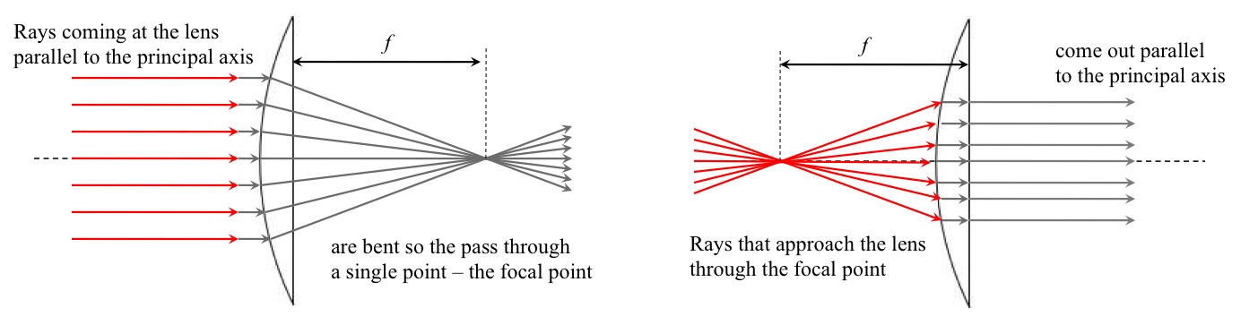
Since light can pass through a lens (in contrast to a mirror), there are focal points on both sides of the lens. For a thin lens, the focal points on the two sides of the lens are equal distances away from the lens (even if it is plano-convex). Rays coming in parallel on one side go through the lens and are all directed to the focal point. This pattern can be reversed: a bundle of diverging rays going to the lens from a focal point are bent by the lens so they all come out parallel.
Typically, these give us two easy-to-find rays: the one that goes parallel to the central axis of the lens and the one that goes through the focal point. The third easy-to-find ray is the one that goes through the center of the lens. This essentially goes straight through.

(The rays do shift a little, but for a thin lens this is a small effect.)
These three rays are shown in the picture from the simulation and any two of them allow us to find an image point.

The three easy-to-find rays are shown in dark blue. The extreme rays in the spray that hit the lens at its edges are shown in light blue. All of the rays in the spray between the light blue rays go through the lens, so the entire lens typically collects rays from every object point! So every point on the lens is collecting rays from many, many object points. Rays coming into the same point on the lens from different object points are coming in from different directions, and when they go through the lens they go out in different directions. Every point on the lens is sorting incoming rays from different object points out to the appropriate image points. Remarkable!
The diverging lens
With the diverging lens the spray of rays hitting the lens spreads even farther apart. An observer getting rays into their eyes on the right of this lens would trace them back to form a virtual image on the same side of the lens as the object but smaller. You can see how this works by playing with the simulation. Click on the image below to link to it.

Pay attention to each of the easy-to-find rays (shown in yellow). It's often difficult to see right away what they are doing. The diverging lens focal points are negative and this can be interpreted to mean that a parallel ray is responding to the focal point on the opposite side of the lens than a parallel ray on a converging lens would. The ray coming parallel from the object bends up (diverges) so that its extension back would go through the focal point on the opposite side of the lens. The ray coming from the object towards the focal point on the opposite side of the lens bends up to go parallel. The ray through the center is the same as one had in the converging lens.
These confusions can be straightened out by using the equations carefully and maintaining careful attention to signs.
Follow-ons:
Joe Redish 4/14/12
Comments (0)
You don't have permission to comment on this page.